Thursday, April 24, 2014

Rafters and Roof

Despite my drawings and thoughts that I had figured the rafter situation out, I found myself having quite a few difficulties with this part. The first job was to get the beam into the correct place and keep it there. With my father's help, we made four stands shaped like upside down T's, centered the uprights on the trailer and screwed them to the top wall plate. Then we screwed the beam to the uprights at correct height and ensured that it was level. My brother also helped quite a bit with this part of the project and helped to lay out the pattern for the first rafter, essentially by setting it against the ends of the wall plate and the beam and drawing on the angles and cut-outs.

This all sounds fairly straight-forward and simple - which it is. However, it still took several tries to get the angles to work out correctly while still keeping the beam in its proper place in the center of everything.

Here are the first few rafters.


And a bunch more all cut out. Marking and cutting was a multiple step and time consuming process, especially as I'm not particularly good at doing things exactly in the same way every time. They turned out pretty well though.

The small blocks on the edges are stapled there as insulation stops. I will be using sheets of polyisocyanurate foam insulation (which has a very high R value per inch) in the roof, but because of the cold climate there needs to be an air space between the insulation and the outer roof. This space helps to keep the roof cold and prevents ice from building up when there is snow on it.
You can buy spacers for this purpose, but they didn't have any in town when I needed them and I thought these blocks would work as well - and also be less expensive.

The first section of rafters are in place in this picture, and you can also see the pony walls on the sleeping loft.

Jumping quickly forward, this picture shows the house with completed rafters and roof sheathing


Another angle. Still no sheathing on the North wall.


Many thanks to my "little" brother for his help!


All of the sheathing on, but no windows cut out yet.


This picture looks down the inside of the building from the door toward the sleeping loft. The walkway over the beams in the center is an old piece of manufactured floor joist, used while we were setting the rafters in place. The roof is tarped down and the open end of the sleeping loft covered with the tarp.

A closer view of the sleeping loft.

So ended the four-day vacation. It was quite a relief to know the roof was up, the tarp was nailed down, and things would be dry. As it turned out, it rained buckets during the night, so the rush to get everything finished to this point was well worth it!


Pony Walls and Ridge Beam

Easter weekend turned into a bit of a full and busy time. I had four days and I had to move the trailer out of the shed where It has been sitting because the roof was too low for the next steps. The weekend turned out to be mostly cold and blustery, which wasn't much fun. However, it didn't rain much, and Sunday actually included some sunshine and a touch of warmth - a good Easter gift.

The roof over the sleeping loft has a different slope than the roof over the rest of the building. It's a much shallower slope which is intended to give more head room and living space in this low-ceilinged part of the house. In order to do this, two short pony walls had to be put in place to hold the wall ends of the rafters up higher. Each wall also has two windows in it for light, ventilation, and fire escape should this ever prove necessary.

Here is one of the walls with the pieces cut and set out, ready to nail together.

Here are the two walls, well nailed and ready to go.


Since I'm using rafters and not trusses, I needed a ridge beam that would run the length of the building, plus extending a few inches at each end. The beam needs to be strong in a vertical direction, but doesn't require a great deal of horizontal strength. I made my beam by cutting 5 1/2 inch strips from a sheet of 5/8 inch fir plywood. I then laminated two layers of the strips together, overlapping all of the joints. The layers were glued together with PL 400 glue and thoroughly screwed (in a good way)   :-) with 1 inch wood screws. This picture shows the bottom layer with the glue applied and the first bit of second layer set on top. The two pieces of OSB are there to act as straight edges to help keep the beam straight while we put it together.


Here's the trailer, moved out of its shed. 

Saturday, April 19, 2014

Little Things and New Toys

I haven't had a lot of time to work over the past two weeks, so not a great deal of progress. However, I was able to get a few things done.


I finished the sheathing on what will be the North side of the house, but haven't cut the windows out yet. I did cut out around the wheel well though, and also finished a few small tasks like the final layer of 2 x 4 around the top of the wall.
 I also spent quite a lot of time sanding the fir beams that hold up the floor of the loft and salvaging some pine siding that will be the ceiling of the bathroom. It also required quite a lot of sanding, as well as sorting out to find pieces that were still intact and able to be used. It was kind of fun to see the the beauty of the boards appearing as the dirt and roughness was sanded off.


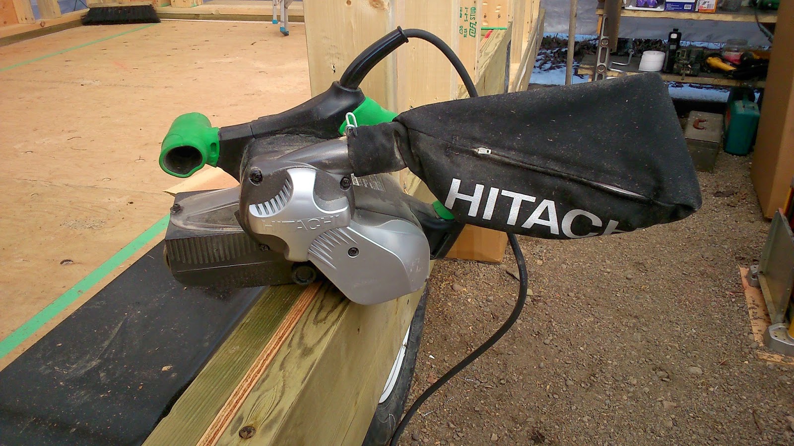
 It was very nice that the new sander that has been on order for a couple of weeks arrived in time. This is a Hitachi with a 3 x 21 inch belt. It works pretty well..


 A couple of other fun toys arrived as well. Due to a fortuitous and very good sale, my father and I went together to buy a new compressor to run the air nailers,

 and a new 12 inch radial arm miter saw, including a folding table. Boy does it make all of the cuts a lot easier and more precise! This is a Milwaukee and so far at least, I'd really recommend it.


I've also been working on figuring out the rafters and the pony walls for the loft. Here's a rough drawing of the rafter angles for the steeper part of the roof. It will no doubt be a bit different than the drawing when it actually goes together, but this helps me to picture it in my head better, and also to get an idea of how much space will be required by all of the roofing layers so I'll know how high I can make the loft.


Sunday, April 6, 2014

The Ceiling Beams and Upper Walls

Height is a big issue for a Tiny House, if you want to be able to pull it down the road at least. There is a limit of 13 feet six inches if you want to be sure to fit underneath things, and also if you want to avoid an over-height permit. This means that every inch of space needs to be carefully calculated and there are some trade-offs along the way.

Since I live in a cold climate, insulation is a big issue. One of the reasons I decided to build my own trailer rather than just buying an RV is that I couldn't find an RV that was really built for winter. (There are some that say they are winter ready. From the research and looking that I did, none of them are very comfortable at -30 or -40, and they use huge amounts of propane trying to stay reasonably warm). In any case, I needed to have an air space between the insulation in the roof and the roof sheeting in order to avoid ice build-up on the roof, and I needed to have enough room to put some reasonable insulation in. (More on insulation later) Therefore, I changed the plan from 2 x 4 rafters to 2 x 6 rafters, and lost a couple of inches of head space in the loft. I decided to transfer this down, and made the ceiling under the loft, and the level of the cross beams, lower than the plan. In my house, the bottom of the beams is at 6 feet 3 inches, and the ceiling under the loft is at 6 feet 6 1/2 inches.

I'm not terribly tall (about 5 foot 8) and so this works for me. It's not great for tall people though.

The interior walls have been added here. You can see angle bracing in the walls, which very effectively cuts out any wobble in the long side walls. The first 4 x 4 beams are set in place here.

The wood for the beams is a red colour and comes from fir logs, cut by a neighbour down the road. The wood is beautiful, but it posed a bit of a problem as the beams were all cut to the full 4 inch by 4 inch size of an un-planed 4 x 4. In order to get them to fit on 2 x 4 walls, and in order to make the height correct, they had to be cut down with the table saw. This proved to be a bit of a grunt for the saw, and required two cuts in order to get through the whole thickness. Thankfully, most of them only had to be cut on one side. Also thankfully, a friend provided a large planer so I was able to run them through and save many hours of sanding. There is still quite a lot of sanding to do, but it's much better. (Thanks again to Jeff!)


The center beam is set here.
This picture shows the beam above the door, and the next beam forward. The plans called for a small loft at this end of the house, but I decided to leave the loft out here as I preferred to have as much of the spacious vaulted ceiling as possible. The second beam is a great place to hang things though, and will allow me to make a shelf at some point if I want or need to.

This picture also shows the first layers of the upper wall construction. You can see the two top plates on the lower wall. These are made so that the ends of the 2 x 4's overlap in different directions in each layer, giving a good corner tie. Next up is the 4 x 4 beam. As you can see, the end beam buts up against a 2 x 4 on edge that runs the full length of the house. The beam is also skirted by a 2 x 4 on the inside that acts as a spacer to extend to the full 5 1/2 width of the rear wall plate.

You can also see that between the beams there is a laminated layer made from a 2 x 4 and a piece of 1/2 inch plywood. This helps to hold the beams in place, and provides a spacer to cover the full 3 1/2 inch thickness of the wall. This continues all the way around the house. The three layers are held together with nails. I'm using a nailgun and have gone through a full box of 3 1/4 inch nails already.

This is the perspective looking from above the door toward the front. The interior walls are in place and the beams for the stepped sleeping loft are also set.

Looking down into the bathroom area from the wall above the sleeping loft, with all of the beams in place. The last layer of 2 x 4 is also in place along the front wall. This is a final layer that runs along the top of everything and ties it all together. It also provides the sill that the rafters will sit on (from the sleeping loft back) and the pony wall will sit on for the length of the sleeping loft. The pony wall will be between 30 and 34 inches high I think (haven't decided that yet) and will give extra space in the loft. The roof over the loft will have a lower slope than the rest of the house.

Saturday, April 5, 2014

The Walls

Once the deck was in place and the floor plan reasonably decided upon, it was time for the walls.

Me and my really cool safety glasses. The front wall is ready to stand up and I'm about to staple the foam sill plate to the deck so that there is a seal between the deck and the bottom plate of the wall.

The first warm sunny day this spring, and the first pick-nick at the Tiny House. My mother, father, niece and nephew, and Chip the dog.
Everybody is enjoying the sunshine. Some of the chickens came to hang out with us for a bit.

The front wall standing and partially sheated.

This will be the north facing wall. The large open space is the large south window - five feet long by about three and half feet high.

The North wall is going up. Note the raised beam at the wheel well. My original plan (as noted in the post about the beam) was to just carry the beam through in one solid line, as it appeared that there would be room to get to the tires. However, after getting the beam all put together, I attempted to remove a tire to be sure. Low and behold, it wouldn't come off.
Several choice explatives later I replaced the tire, cut out the section of beam that ran along the wheel wells, made a new laminated section for each side, and put it up on blocks so that it would cross the wheel space higher up. This was all nailed together and reinforced with metal plates nailed across the joints and securing the upper beam, block, and lower beam.

This is the floor plan, more or less, taped out to see how it will fit. Since my drawing didn't have dimensions and since the trailer wasn't exactly the size of the scale drawing, there was quite a bit of figuring and improvising along the way.

Laminating the posts for the rear shear wall. As I mentioned earlier, I did buy plans from the Tumbleweed company and used them as a back-up reference, especially for construction tips. The rear shear wall is intended to provide a very solid and stable brace structure that will keep the rest of the walls from shifting or swaying when the trailer is moving around.

The Tumbleweed plans called for engineered beams. I couldn't find them, so made my own instead. These are made from 3 layers of 2 x 6 and 2 layers of 1/2 plywood all glued and thoroughly nailed together. This makes a square post 5 1/2 x 5 1/2 inches, which fits nicely on the 2 x 6 plates for the rear wall. This is only 2 x 6 wall. The rest are built from 2 x 4.

The rear wall is up, but the plates haven't been cut out of the bottom of the door yet. The rear windows have grown a bit.

Looking back from about the level of where the fridge will be.


The Floor Plan

Getting this plan done was actually a task that took several months and involved a great deal of research into the appliances and fittings that I wanted to include so that I would have a reasonably exact idea of the cut-out size of each one. A tiny house requires everything to have a place and every inch counts. I'll talk more about the appliances later.

I started with the floor plan that came with the plans I bought from Tumbleweed Homes. However, my house was quickly becoming completely different than the plans and so I needed some new ideas.
I started by drawing my own rendition of a floor plan. However, to my great good fortune, my aunt is a very accomplished interior designer with a knack for many things, including finding great ways of using small spaces. With the help of my uncle, who converted her sketches to the diagrams you see here, she helped me to find some great ways to utilize the space to best advantage. This was such a vast improvement over my initial drawing that I haven't included my first try.

Huge thank you's to Barbara and Caryll Goetze for all of their work and expertise in getting the design imagined and drawn out!

This is more or less the final plan. Measurements are not included, but the scale of the original drawing was 1/4 inch = 1 foot. An elevation of the walls is included adjacent to each side. Starting from the top left and going clockwise there is a closet (also containing water tank, electrical panels and possibly batteries for a solar system), chest of drawers, shower, bathroom sink, once piece front load washer/dryer, hot water tank (not pictured) and toilet.

The toilet is sided by a short wall, and across from this is a pantry, then a fridge and a built-in desk. I plan to make a roll top so the back half can be covered, leaving half of the desk space as extra kitchen space if needed.
The kitchen is fairly self evident. I will probably add a swing-up extension for the end of the counter. The dotted lines on the counter show where a raised set of cupboards was planned. I think I will keep this space open, however. I may drop the counter edge at the dotted line and make it a swing up extension as well. This will serve as a breakfast bar, and will be easier to build as I'm planning to make the counter tops by laminating fir 1 x 4's and I only have a 12 inch planer.

The dotted lines in the middle of the floor are for an Asian style low table that I started to build a few years ago. It will slide into a niche under the kitchen counter. The bench along the side will open for storage and will also have a swing up extension so that it can double as an extra bed.

I decided to join the big windows on the right so that they are one larger window. Some of the other windows have also been extended as I want to have lots of light to help the space feel larger by opening it to the outside as much as possible. The trailer will be parked so that the large windows face to the south.


The Deck

After the beam, the deck was pretty simple. I used 3/4 inch tongue and groove standard plywood, glued and stapled with 2 inch staples. (Thanks to Jeff for loan of the big staple gun).

Just starting to go between the wheel wells. This is me, stapling the heck out of the floor.

PL 400 glue on the deck boards and silicone to seal the top of the plywood layers in the beam. The 2 x 8 and 2 x 6 are treated so they will handle moisture. Note that the beam no longer continues past the wheel wells in this picture. More on this later.

The deck is done. This picture also shows two of the ready-rod bolts I had welded to the frame. There are two in front and two in back to help hold the structure tightly to the frame. They will run through the bottom plates of the front and back walls.
Also note the handy-dandy tool and everything else shelf at the back of the tent. It was well worth the extra hour or so to build it as it would be a constant mess and hard to find things without it.

The Outside Beam

The beam around the outside turned out to be quite a time-consuming little project. It involved four layers:

  • A 2 x 8 outside layer
  • A layer of 1/2 inch plywood glued and stapled to the 2 x 8 to laminate the joints
  • A layer of 1/4 inch plywood as a spacer to go between the 1/4 inch metal plates
  • An inside 2 x 6 layer running on the inside of the metal plates and between the welded extensions. This layer sandwiched the metal plates and added the extra support of fitting inside the channel of the channel iron. Each of these pieces had to be shaped at the ends in order to fit into the "C" of the channel iron and to make space for the welds.
  • About 72 3/8 inch bolts to hold the beam to the trailer, and lots of nails from both sides to complete the lamination.

This picture shows a clear view of the four layers. The front is just one 2 x 8 held to the front metal beam with self threading metal screws that I took out of the deck boards I removed. It is there so that there is something to nail to. You can also see the bolts inserted temporarily to hold the outside beam in place. The inside layer of the sandwich only has one piece completed.
Also notice that the beam carries directly through at the same level as it passes by the tires and the wheel well. This was a mistake. More on that later...

My father attempting to drill a pilot hole in a difficult location. Dad's done a lot of building and his experience and help have been invaluable. All of the construction is being done inside the large fabric covered frame that he uses as his boat house, and he moved his boat out to make room. The many tools required for the job are also a collection of tools from my father, my own tools, and a few borrowed from my brother - so many many thank you's to my father and family for all of their support and assistance!

Another view of the layers of the completed beam. This is also a good view of one of the scissor jacks.
You can also see some wires hanging out here. This was another little job that ended up taking quite a lot of time. All of the lights had to be removed and extensions added to the wires so that they will reach out to the new sides. I used heat-shrink couplers for the wires, heated them with a small torch, and then wrapped each joint with electrical tape for good measure.


The Trailer

So, the starting point is a trailer. Things to think about with the trailer:

- height from the ground. A car hauler is best as it's close to the ground and gives more room for living space before you hit the 13 foot 6 inch height limit. However, it's also very narrow.
- Number of axles and load limit. I bought a 24 foot trailer with two 7000 pound axles, for a total load of 14,000 pounds. This is hopefully going to be enough. (A comparable 24 foot tiny home from Tumbleweed Tiny Homes weighs about 10,500 pounds including the trailer and finished house but not including content.
- Used, new, and trailer quality. I bought a new trailer, but one on the relatively low end of the cost scale. It seems to be solid enough, but lots of corners were cut with paint, rust proofing and finish work. It was difficult to find a used trailer of the length I was looking for in my area, so new was my only choice. This trailer was about $6,500.00

Here's the Trailer, just arrived.

A first permutation of my floor plan chocked out on the deck.
After fiddling with floor plans for a bit, I decided that the 6 foot ten inch maximum space I was going to get wasn't quite enough. So, next came the extension scheme.

The trailer frame is built from 6 inch channel iron sides welded to three inch channel iron cross pieces. After consultation with a welder and local man who builds trailers for a living, I decided that adding a fourteen inch extension to each side could be safely supported.

The extensions make my trailer wider than the legal limit, and I will therefore require a permit to transport it. However, in BC at least, a trailer can be up to 10 feet 6 inches wide (night and day travel) or 11 feet six inches wide (day travel only) and not require a pilot car. Wide load permits are relatively inexpensive and not difficult to obtain. As I won't be moving my trailer often, this should not cause major difficulties.

Here you see 6 inch channel iron extensions welded to the trailer frame. The end of each extension has a 4 by 6 inch rectangle of 1/4 inch plate steel welded on. Each plate has four 3/8 inch bolt holes drilled in it so that a beam can be bolted to the outside.
If you are planning to make your own tiny house and want to try the extension idea, please note that this has not been approved by an engineer. I checked it out as best I could with people who are knowledgeable about the strength and stress capabilities of steel and of welds, including a professional welder who builds high quality trailers. However, if you follow a similar plan, please know that you do so at your own risk.

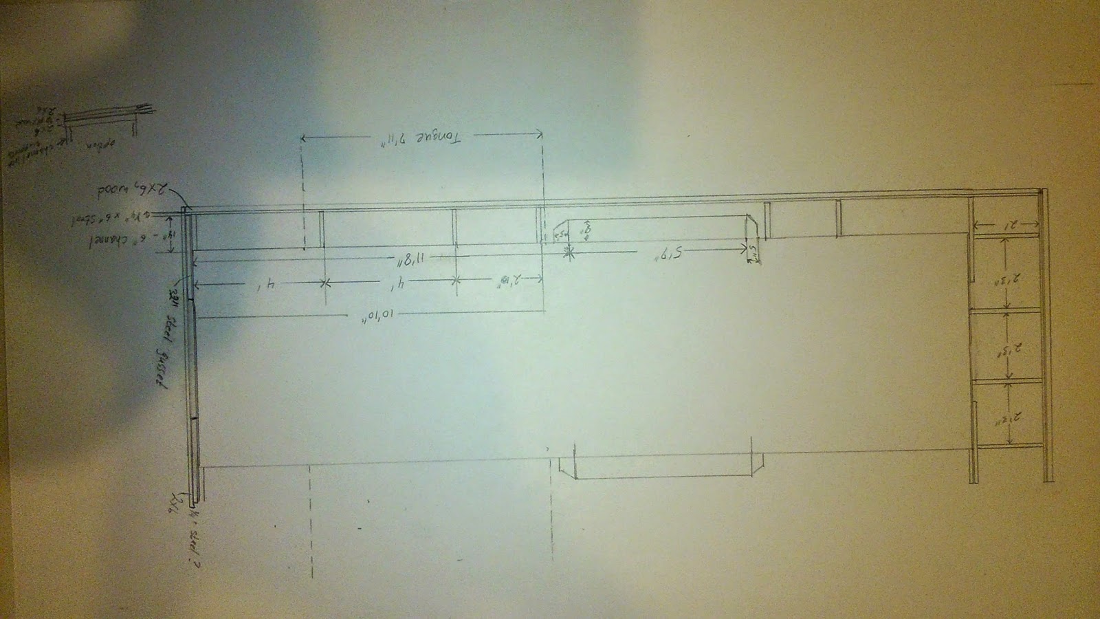
The drawing I made for the extensions to take to the welder.

Since I was extending things anyway, I added an extra 27 inches to the back for a deck. I'm not sure exactly why I chose 27. I didn't want to put too much torque on the rear trailer rail as it doesn't have any supports welded to it, and I wanted to have enough space to make the deck reasonably worthwhile. This is where it came out...

To save on some of the weight, and because the extra boards were not really necessary, I removed half of the decking. Here you can see the beginnings of the beam on one side as well.

The trailer with beam started. You can also see the scissor jacks here. I had these welded on when the extensions were added. I'd say that they are essential for leveling and stabilization.